The solid workflow: the Frame-Wing
This page builds a finite element model of solid bricks in the app, in the same order a part is drawn in CAD: solid shapes are added, copied in rows, subtracted and joined, then meshed; the parts are bolted together by merging nodes, and the model is solved. Everything on this page is done with the mouse and the keyboard, and the demonstration module builds the same models with the same steps.
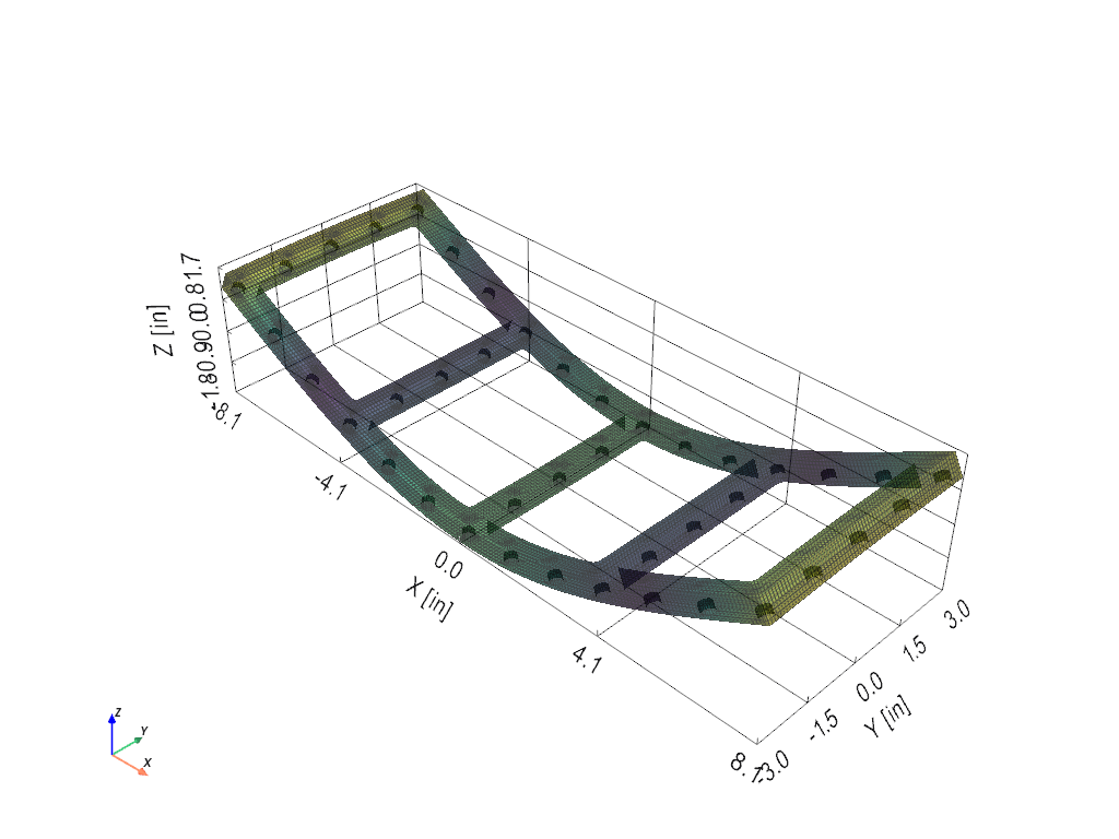
The structure is the Frame-Wing, a small aluminum frame with two wings that the structural dynamics community shares as a test article for substructuring. The frame is a 16 by 6 in ladder cut from half-inch plate, with two rails and five uprights half an inch wide and 41 threaded steel inserts to bolt things to. The two wings are rectangular, 22 by 4.385 in, one thin (1/8 in) and one thick (1/4 in), and either screws across two of the frame's uprights. Its solid models, finite element models and test data are shared on the SEM Dynamic Substructuring Focus Group wiki, https://wiki.sem.org/wiki/Round_Robin_Frame_Structure. Every dimension below was read off the finite element models shared there.
A half-inch bar spanning a 100 mm window is neither a beam nor a plate. The BARC is built from planes of plate elements because its walls are thin. This frame is built from eight-node solid bricks with incompatible bending modes, so a single brick through a plate's thickness bends the way the plate does.
from visualdynamics.demo import frame_wing

frame_wing.project().save('frame-wing.vdyn')    # the five models this page builds
The project's journal (the console) records this page's steps, one line per click.
| Step | Where | How |
|---|---|---|
| Start a geometry | the project row's bar | + New Geometry |
| Add the shapes | the geometry's Solids row | Add Block, Add Cylinder, Add Cone, Add Sphere, Add Section, Add Plate, Add Disk |
| Pattern them in rows | solids picked in the tree | Pattern |
| Cut and join them | solids picked in the tree | Subtract, Union |
| Mesh | parts picked in the tree | Mesh Solids |
| Bolt a wing on | element groups picked in the tree | Mate Surfaces |
| Give each part its material | the pencil on an element group's row | the Element Groups table |
| Solve | the geometry's 3-D view bar | Modes, then Solve Modes in the pane |
1. The frame, as solids
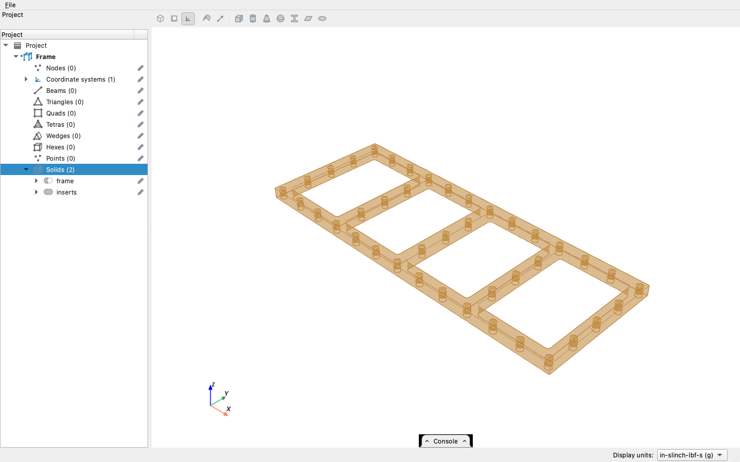
Choose the inch system in the unit menu, select the project's row and press + (New Geometry), then rename the new geometry Frame. Select its Solids row and add each shape below with Add Solid Block or Add Cylinder. The pane beside the 3-D view takes a center, the size (three widths and a corner radius for a block, or a radius and a length along Z for a cylinder) and a name. It draws the shape as you type, and Add puts it in the tree.
| Shape | Add | Center | Size | Name |
|---|---|---|---|---|
| plate | Block | (0, 0, −0.25) | 16 × 6 × 0.5 | frame |
| window | Block | (−5.8125, 0, −0.25) | 3.375 × 5 × 1, corner 0.138 | |
| rail hole | Cylinder | (−7.75, −2.75, −0.25) | radius 0.1451, length 1 | |
| upright hole | Cylinder | (−7.75, −1.375, −0.25) | radius 0.1451, length 1 |
The window is deeper than the plate so that it cuts all the way through. Its corner radius rounds its four edges along Z, so once it is cut from the plate it leaves the 0.138 in fillets the frame has in each window's corners. Without the fillets, the frame's in-plane modes come out 8 % low.
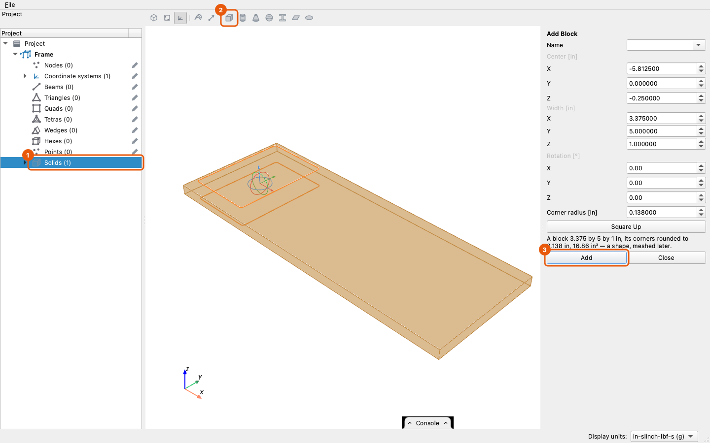
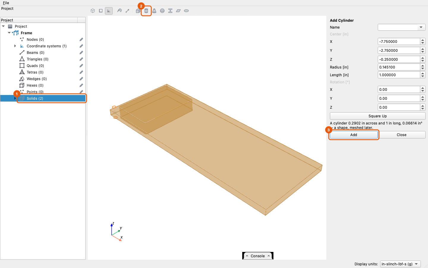
Then pattern the shapes. Pick a solid in the tree and press Pattern. The pane asks how many copies along X, Y and Z, counting the original, and how far apart, and draws the copies as you type. Pattern makes one solid, the pattern, with the original under it in the tree, and picks the pattern for the next step. The copies follow the original: the original's pencil changes every copy, and the pattern's own pencil changes how many there are and how far apart. One pattern can be a whole grid, so all 26 rail holes are one hole patterned 13 along X by 2 along Y.
| Pick | How many along X, Y, Z | Spacing along X, Y, Z |
|---|---|---|
| the window | 4, 1, 1 | 3.875, 0, 0 |
| the rail hole | 13, 2, 1 | 1.291667, 5.5, 0 |
| the upright hole | 5, 3, 1 | 3.875, 1.375, 0 |
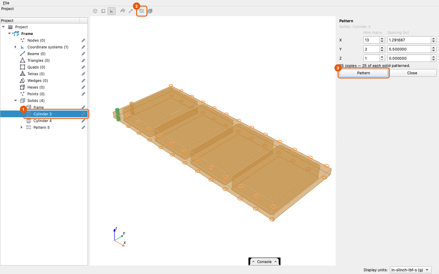
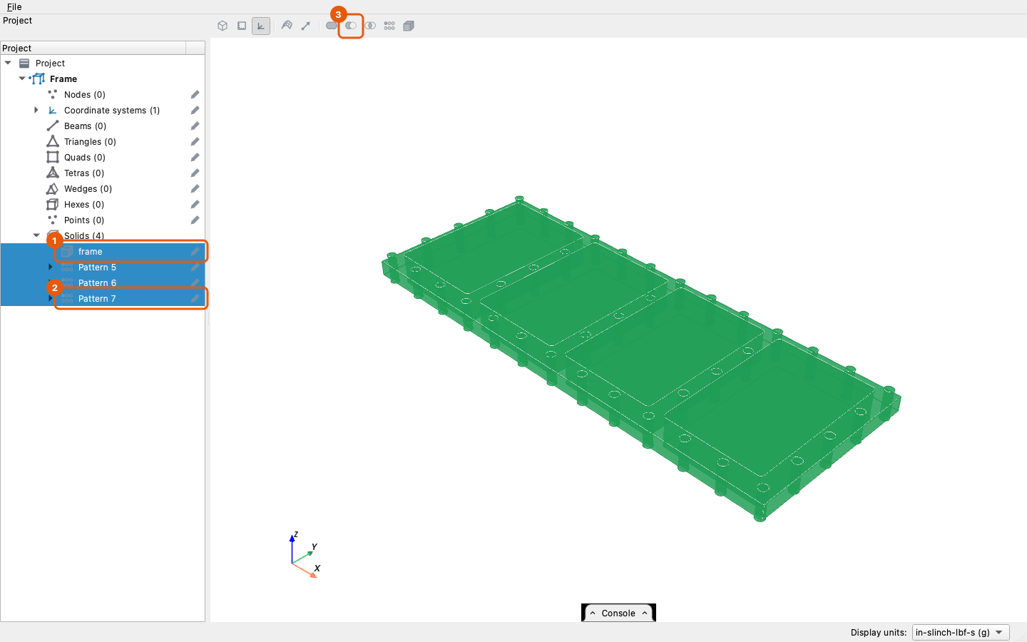
That gives four windows, 26 holes along the rails and 15 down the uprights (41 holes in all), in three patterns. Now pick the plate and the three patterns (click the plate, then Shift-click the last pattern) and press Subtract. Subtract takes the other solids from the first one in the tree, here the plate, and its tooltip names which one that is. The result is named for the plate, frame. Union makes the picked solids one, Intersect keeps only what they share, and Take Apart undoes a boolean or a pattern so its solids stand on their own again.
The inserts fill the top 5/16 in of each hole. Add the same two cylinders again, centered a little higher and shorter, named inserts, and pattern them the same way as the holes:
| Shape | Add | Center | Size | Name |
|---|---|---|---|---|
| rail insert | Cylinder | (−7.75, −2.75, −0.15625) | radius 0.1451, length 0.3125 | inserts |
| upright insert | Cylinder | (−7.75, −1.375, −0.15625) | radius 0.1451, length 0.3125 | inserts |
Pick the two patterns and press Union to make one part, inserts.
2. Mesh
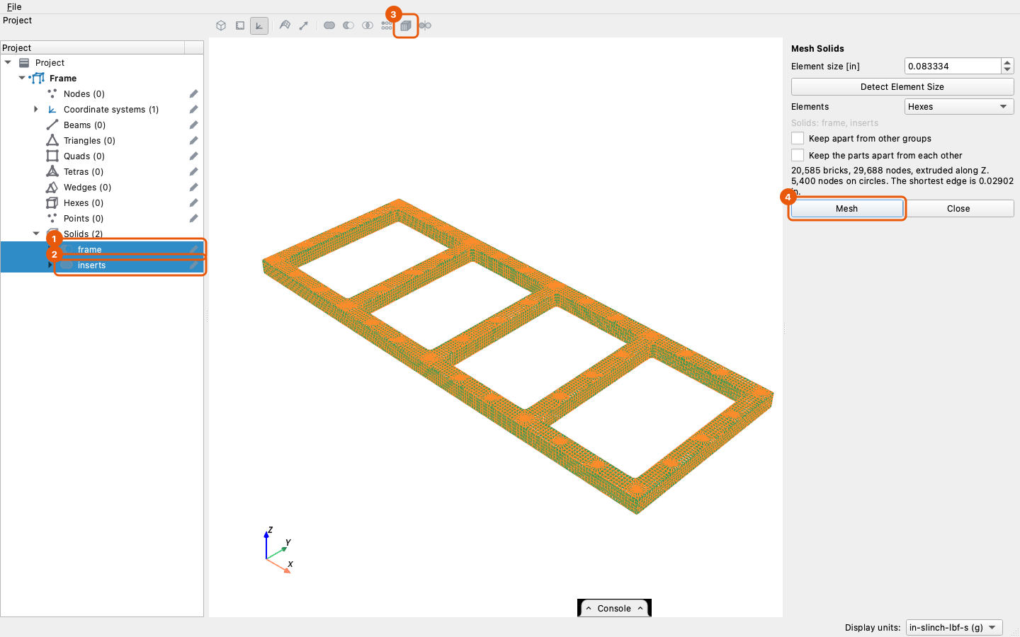
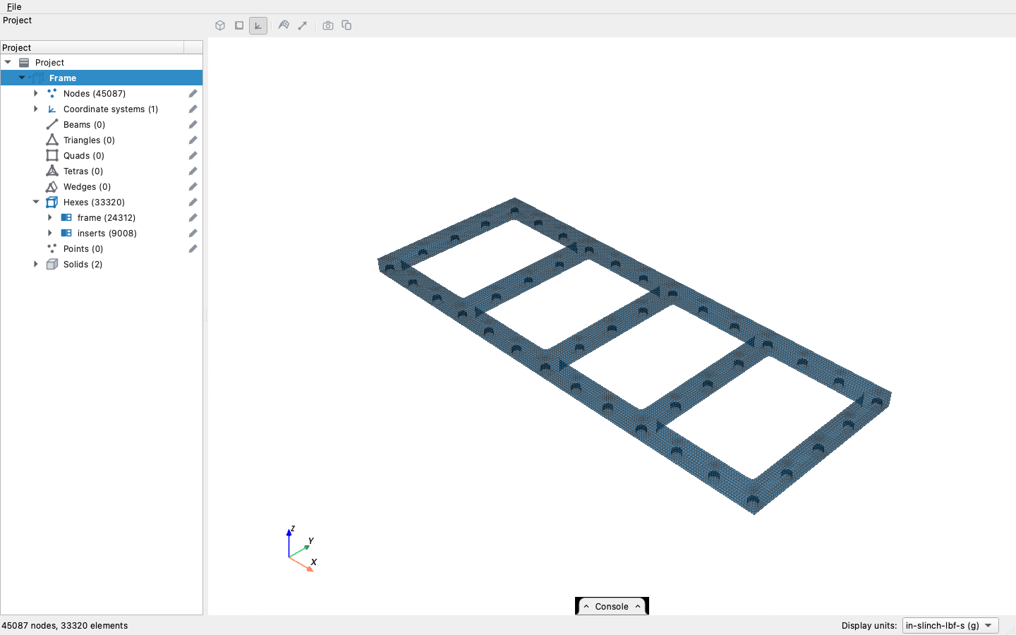
Pick frame and inserts in the tree and press Mesh Solids. Leave Elements on Hexes: the frame is an extrusion along Z, which is what bricks mesh best. Type 0.083334 for the element size (a twelfth of an inch, which is six bricks across a member and three across a hole) and press Mesh. The twelfth is rounded up in its last place on purpose: a span that falls exactly halfway between two brick counts then takes the count this model was checked with, where 0.083333 would give some of them one brick more. The pane opens on half the thinnest feature as its size. Each part becomes an element group under Hexes, and the two share their nodes around each hole. Each hole is meshed as rings of bricks about its circle, with a square core where an insert fills it, and the fillets are rounded. The frame comes out at 33,320 bricks and 45,087 nodes. If you change a solid and press Mesh Solids again, each part's new bricks replace its earlier mesh, and its element group and material are kept.
3. Materials and solve
Select the element groups' rows in the tree (Shift-click to take them all) and click the pencil on one of them: the Element Groups table opens with a column for each group selected. An element group of solids takes a material and nothing else.
| Element group | Material |
|---|---|
| frame | 6061-T6 |
| inserts | typed: modulus 1.1216e6 psi, density 3.6175e-4 lbf·s²/in⁴, Poisson's ratio 0.3 |
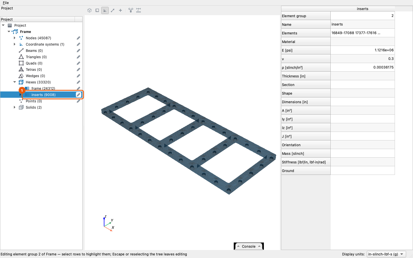
The inserts' numbers are the shared model's: a stiffness tuned to the tested frames and a density that gives the frame its measured mass, spread from the insert's annulus over its whole hole. Select the geometry, turn on Modes and press Solve Modes in the pane. It solves in about half a minute, with six rigid-body modes at 0 Hz followed by the elastic modes.
4. The wings
Each wing alone is a geometry of its own: a plate with eighteen holes, made by 1 in long cylinders through it. For the thick wing (the thin one is the same with 0.1243 for the thickness and 0.08975 for every Z):
| Shape | Add | Center | Size | Name |
|---|---|---|---|---|
| wing | Block | (1.9375, 0, 0.15575) | 4.385 × 22 × 0.2563 | thick wing |
| screw hole | Cylinder | (0, −2.75, 0.15575) | radius 0.1043, length 1 | |
| rail hole | Cylinder | (1.2917, −2.75, 0.15575) | radius 0.1043, length 1 | |
| end hole | Cylinder | (0.5626, −7.75, 0.15575) | radius 0.1043, length 1 |
| Pick | How many along X, Y, Z | Spacing along X, Y, Z |
|---|---|---|
| the screw hole | 2, 5, 1 | 3.875, 1.375, 0 |
| the rail hole | 2, 2, 1 | 1.291667, 5.5, 0 |
| the end hole | 2, 2, 1 | 2.75, 15.5, 0 |
Subtract the three patterns (eighteen holes) from the wing, mesh it at 0.125, and give it 6061-T6. The wing's underside is 0.0276 in above the plane of the frame's top (z = 0), the thickness of the washers that go under it on the frame.
5. A wing bolted to the frame
The wing on the frame is one geometry. Before meshing the Frame geometry, copy it (Copy, then Paste on the project) and rename the copy Thick Wing on Frame. In the copy, add the screws, then repeat the wing's steps, then bolt the two together.
The screws
Each screw is threaded into the insert under it, and the steel there is what makes the joint stiff. In the copy, add a cylinder over one insert at a screw, named screws, and pattern it into four. The pattern takes the cylinder's name, screws:
| Shape | Add | Center | Size | Name |
|---|---|---|---|---|
| screw | Cylinder | (0, −2.75, −0.15625) | radius 0.1451, length 0.3125 | screws |
| Pick | How many along X, Y, Z | Spacing along X, Y, Z |
|---|---|---|
| the screw | 2, 2, 1 | 3.875, 5.5, 0 |
Then mesh frame, inserts and screws together at 0.083334. Where two parts overlap, the later one in the tree takes the bricks, so the four inserts under the screws become steel.
The wing and its washers
Add the wing's shapes (section 4), and a washer under the wing at each screw, patterned the same way as the screws:
| Shape | Add | Center | Size | Name |
|---|---|---|---|---|
| washer | Cylinder | (0, −2.75, 0.0138) | radius 0.196, length 0.0276 | washers |
| Pick | How many along X, Y, Z | Spacing along X, Y, Z |
|---|---|---|
| the washer | 2, 2, 1 | 3.875, 5.5, 0 |
Pick the wing and the washers, press Mesh Solids, type 0.125, tick Keep apart from other groups, and press Mesh. The washers share nodes with the wing above them, and their undersides lie on the frame's top without sharing any node with it.
Bolting
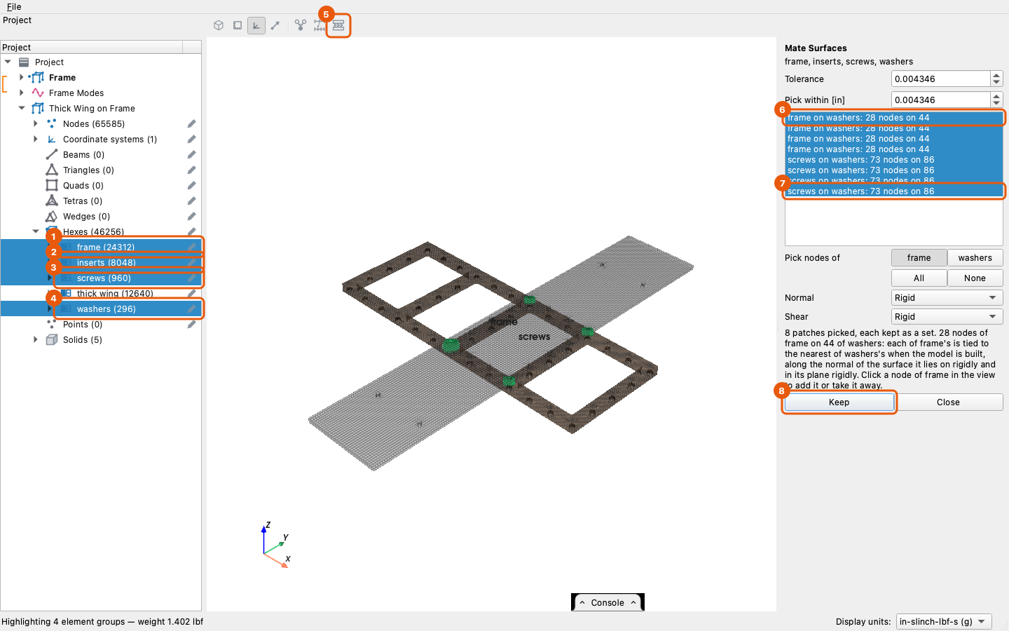
The washers and the frame were meshed separately, so their nodes do not line up, and they do not need to. Under Hexes, pick the element groups frame, inserts, screws and washers and press Mate Surfaces. Each washer's underside rests partly on its screw and partly on the frame around it, so the pane lists eight patches, two at each washer, and marks them all. Click the first in the list and Shift-click the last to pick all eight, leave Normal and Shear on Rigid, and press Keep. Each patch becomes a joint under the geometry's Mated Surfaces row, and the wing is bolted on: each node on one side is held to the point of the other side's surface beneath it, so the two meshes need not match.
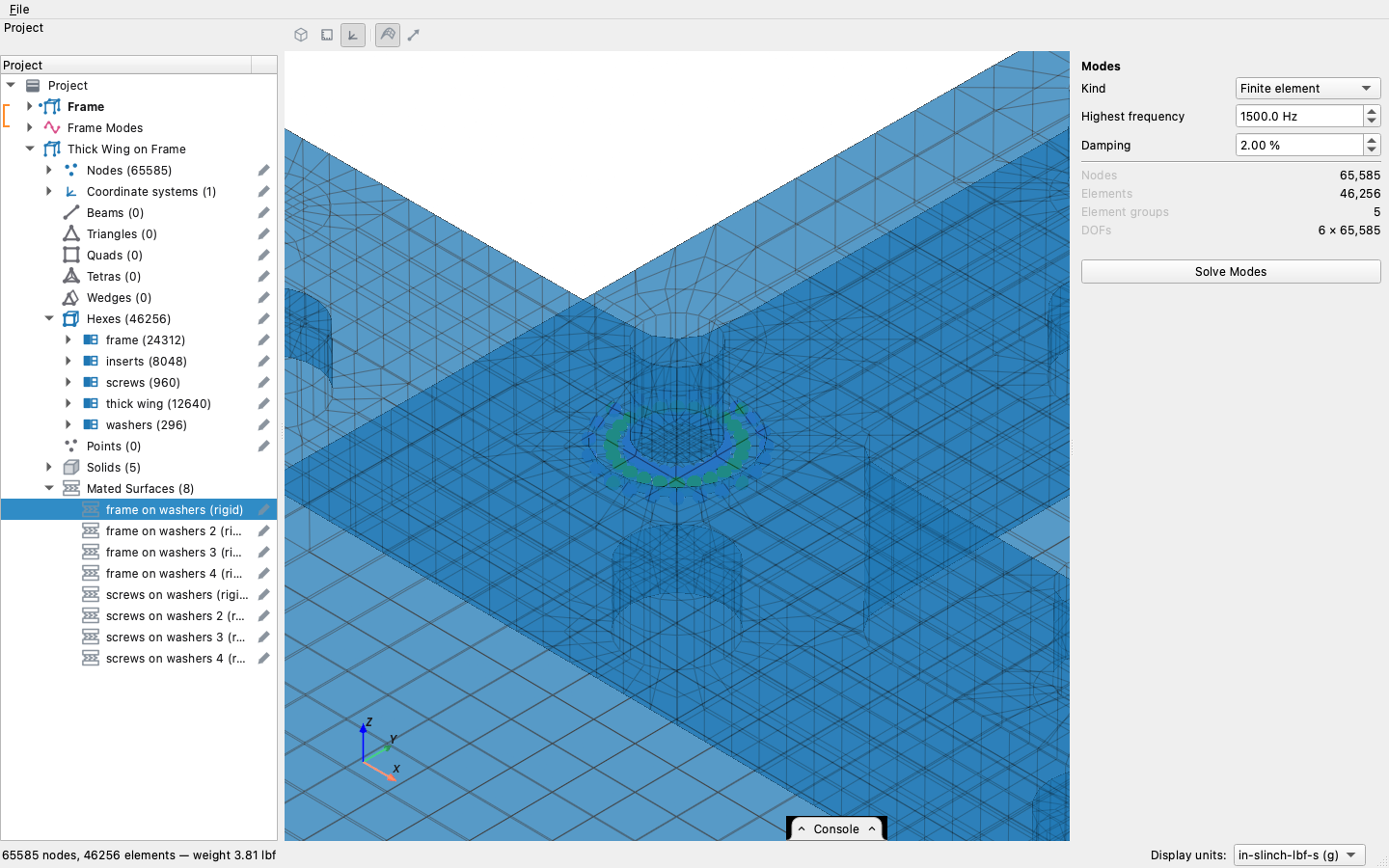
A joint can be made softer than rigid. Its pencil opens it again, where Normal and Shear each take Stiffness and a value per node, which is how a bolted joint is tuned to match measured modes.
The screws' heads
The rest of each screw's mass, its head and the washer under the head, sits on the wing's top. Click the pencil on the Points row, switch on add mode (+), choose New element group, and click the node of the wing's top nearest each screw. Name the group screw heads and give it a mass of 1.9986e-5 lbf·s²/in (3.5 g) in the Element Groups table. Give screws and washers 1018 steel.
Select the geometry and press Solve Modes in the Modes pane. The thick wing on the frame has 65,585 nodes and solves in under a minute.
Sections, tubes and holes
The frame is a block with holes, but a fixture or a stand is more often built from rolled shapes. Add Section on the Solids row adds one as a single solid. Pick the shape (I-beam, channel, tee, angle, rectangular tube or round tube), type its dimensions and a length, and it runs that length along its own Z, and can be turned like any other solid. The dimensions are the same ones the beam element's sections take, so a channel is its depth, flange width, flange thickness and web thickness:
| Shape | Dimensions | Laid across its own axes |
|---|---|---|
| I-beam, tee | depth, flange width, flange thickness, web thickness | depth along Y, flange along X; a tee's flange at +Y |
| channel | the same | the web at −X, the flanges running to +X |
| angle | long leg, short leg, thickness | the heel at −X, −Y, the long leg along X |
| rectangular tube | width, height, wall | width along X, height along Y |
| round tube | outer diameter, wall |
A section's center is the middle of the box it fills. Its pencil opens the pane on its dimensions, so making a beam deeper is one number changed. A section meshes the way the blocks it is made of would: its flat faces on grid lines, and a round tube as a ring.
A hole is a cylinder subtracted from the part, as the frame's are, and a
counterbore is a second, wider and shorter cylinder at its entry. A
script can add a hole in one call: add_solid_hole takes the center
where it enters and runs down its own Z, through the part it is cut
from when no depth is given, and stays through if that part is made
thicker. Pick the part and the hole and subtract as before:
import visualdynamics

project = visualdynamics.Project('Stand')
project.new_geometry('Stand', unit='in')
beam = project.add_solid_section('Stand', 'I-beam', (0, 0, 12), (4, 2, 0.25, 0.2),
                                 24, unit='in')
plate = project.add_solid_block('Stand', (0, 0, -0.25), (8, 8, 0.5), unit='in')
hole = project.add_solid_hole('Stand', (3, 3, 0), 0.25, counterbore=(0.44, 0.19),
                              unit='in')
base = project.combine_solids('Stand', 'subtract', [plate, hole])
What was checked
The model was checked three ways.
The element
The finite element model of the frame shared on the wiki was read with the Nastran importer and solved in Visual Dynamics. Its first ten elastic modes match the ones MSC Nastran gives for the same mesh to within 0.1 %, which checks the brick element and the sparse solver separately from the meshing.
The frame and the wings, against test
The wiki lists the first nine modes of five frames, which differ from each other by up to 5 %. The frame built here is within 1 % of frame SN003 on six of those modes and within 4 % on the three in-plane modes. The wings' frequencies were fitted from the shared test FRFs with Fit Modes: the thin wing is within 1 % on every mode, and the thick wing within 3 %.
| Frame mode | Measured, SN003 | Built here |
|---|---|---|
| 1 | 234.2 | 235.1 |
| 2 | 291.7 | 291.7 |
| 3 | 624.4 | 628.8 |
| 4 | 652.8 | 652.9 |
| 5 | 715.3 | 696.0 |
| 6 | 752.0 | 725.1 |
| 7 | 1118.8 | 1124.5 |
| 8 | 1155.3 | 1160.9 |
| 9 | 1241.3 | 1214.6 |
The wings on the frame, against the shared models
Finite element models of the same assemblies are shared on the wiki, tuned there to test (Linderholt, 2024). Each of the first nine modes built here is within 3 % of them. The shared models join each wing with rigid links between the screws' parts, which their author notes may make them slightly stiffer.
| Mode | Thick wing on frame, shared | Built here | Thin wing on frame, shared | Built here |
|---|---|---|---|---|
| 1 | 126.0 | 124.5 | 63.8 | 62.3 |
| 2 | 233.4 | 239.3 | 113.5 | 111.6 |
| 3 | 242.7 | 241.1 | 224.4 | 222.6 |
| 4 | 312.4 | 308.7 | 224.8 | 225.2 |
| 5 | 439.3 | 438.0 | 268.6 | 270.4 |
| 6 | 454.3 | 451.2 | 306.2 | 302.7 |
| 7 | 460.8 | 464.9 | 373.0 | 366.0 |
| 8 | 645.1 | 651.5 | 417.2 | 410.8 |
| 9 | 676.5 | 678.1 | 497.2 | 491.5 |
The steel screw threaded into the insert, as on the hardware, matters: with only a washer mated onto the insert's spread-out material, the thick wing's first mode reads 7 % low. No property was adjusted to bring these numbers closer. None of the wiki's files are in this package or its examples; the numbers above are the values read from them.
From a script: